Cloud-based IoT control systems remotely monitor not only dust collector conditions, but universally monitor emissions, airflow, vibration, humidity, high temperature or any other data set, from anywhere on most any equipment around the globe. This increases the use of predictive maintenance.
Joe Haney, Product Manager for Fine Filtration and IAC's SMART Plant Remote Monitoring Technology, gave a presentation at the 2023 IEEE-IAS/PCA Cement Conference on the topic of utilizing IoT technology to connect cement plant processing systems to monitoring software which allows cement plant personnel to remotely monitor machine operations, thus saving valuable maintenance time and reducing the potential for unexpected down time.
Following is the abstract and paper submitted by Joe Haney to the event committee. It is also available as a PDF: Virtual Reliability Manager - How to Become the SMART Cement Plant of Tomorrow Today
Virtual Reliability Manager Abstract
Remote Monitoring Platforms automatically deliver critical real-time data to cement plant personnel around the globe with cloud connected controls and sensors. This paper reviews IoT technology for use in the Cement Industry to:
• Maximize efficiency – aligns with goals of increased automation
• Decrease energy consumption and operating costs through optimization
• Assure Health, Safety, and Environmental compliance through awareness and mitigation
• Provide ‘virtual’ equipment health checks
Four Case Studies review five findings of interest:
i. Reduction—unplanned outages
ii. Insight—mechanical failures predicted before occurrence
iii. Simplification—Ease of access to information
iv. Optimization —Eliminate unwanted movement from maintenance work
v. Accuracy & Efficiency -Error-free record keeping
Index Terms—Energy, Filtration, Industry 4.0, Internet of Things, Maintenance, Sensors, Temperature, Digital communication, Optimization.
I. NOMENCLATURE
Transport Layer Security (TLS) – a standard protocol that provides authentication, privacy and data integrity between two communicating computer applications
II. INTRODUCTION
Using a device that is connected to the internet is routine in our personal lives, but only recently has become more common for industrial manufacturing equipment unassociated with plant PLC systems. The purpose of this paper is threefold:
III. What is IoT technology
IV. What are the four goals of IoT technology
V. What are real-world examples of IoT being applied successfully
III. WHAT IS IoT TECHNOLOGY?
IoT (Internet of Things) devices are defined as any device that functions as a “gateway” to the internet. This means that IoT, or Gateway devices are connected to the internet and send data to a predetermined location, i.e., ‘the cloud’. Gateway devices connect to or replace traditional plant monitoring equipment. This paper will focus on gateway devices that are designed to control baghouse operation and cleaning as well as measurables associated with dust collection performance, such as temperature, pressure, and energy consumption.
The systems discussed in this paper do not require ethernet connection to a plant PLC, and are considered maintenance systems, not control or compliance systems. All data, process readings, and metrics measured by the IoT hardware referenced in this paper are transmitted to the Cloud over a Cellular connection, such as ATT or T-Mobile. Best practice for IoT connectivity requires TLS (see nomenclature) security which is utilized on the systems referenced in this paper.
Every device is unique and highly encrypted. Devices that use TLS security should have data that is encrypted at the device (before transmission) and are decrypted only after secure Cloud endpoints. This provides fully encrypted data during transmission.
IV. WHAT ARE THE FOUR GOALS OF IoT TECHNOLOGY?
A. Connect
Many plants have sophisticated PLC systems designed to provide visibility and control over their largest and most critical systems. Baghouse systems can easily display temperature, pulse counts, and differential pressure locally, but also in a central location for visibility, record-keeping, and reactive maintenance recommendations.
In many other industrial installations, equipment is not connected to a central PLC type system, and would benefit from remote access, such as for remote or, moving equipment and baghouses that are far above grade, or in unsafe areas of the facility. Gateway technology should be considered for these applications. Once installed and powered, gateway devices automatically connect to a local cellular signal. When connected to a cellular signal, sensors (analog or digital) of the end-user’s choice are connected to the gateways and transmit this information (i.e., differential pressure, temperature, vibration, flow, humidity, bearing temperature, etc.) to a web portal for secure and immediate use where and when needed by the user.
B. Collect
With baghouses, there is critical data to capture in order to assess and improve performance. Some plants require a written recording of differential pressure on a daily or weekly basis. Other baghouses can “run” for weeks, even months, without any recorded data. If you do not have operational data, you do not have a benchmark for which you can begin to make any intelligent maintenance decisions. Datalogging should be utilized well beyond one or two monitoring points per day.
C. Predict
If you know your car tires will be unsafe at 50,000 miles, you should expect problems if you drive them to 60,000 miles. That’s corrective maintenance. If you change your car tires at 40,000 miles instead, you’re now performing preventative maintenance (Fig.1). You prevented the problem from happening. Not bad, but in terms of maintenance, you might be jumping the gun and could get another season of use out of that set of tires.
Dust collector filters are similar. Even when a dust collector is maintained and operated optimally, filters are moving parts and will eventually mechanically fail. The data collected through connected IoT control systems (pulse count, temperatures, differential pressure) provides key predictive insight as to when the filters will fail, which in many cases will extend filter life, assuming filters are normally changed on a preventative basis.
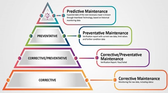
Fig. 1[b1] – Maintenance Pyramid
With cloud-connected gateway technology, you can implement predictive maintenance decisions using data provided by these IoT connected devices. Once installed, IoT devices start automatically collecting data. They allow the user to remotely observe a vibration sensor in real time and know and predict what frequency and length of time it takes for damage to occur to equipment. Seamlessly remotely track differential pressure and cleaning cycle performance over the course of an entire manufacturing campaign to know just how long moving parts (filters, cleaning system diaphragms, solenoids) are going to last.
Once installations are mature, equipment that is being remotely monitored for years will provide high-value operational data allowing you and your staff to determine how to best manage your time and resources for critical equipment. Eliminating unexpected downtime is an invaluable and typical benefit from an IoT implementation.
D. Improve
Finally, the end goal of connected technology is to allow manufacturing facilities to improve the process. Intelligently designed gateway connected systems should allow for customizable alarms (high and low). Who should be notified about upset conditions? How many users do you want accessing the data? How do you trend the data to determine what is and what isn’t contributing to upset conditions? It’s entirely up to end-users to utilize the information to maximize their staff, inventory, and outage decisions and maximize efficiencies. Data overload can easily be achieved so being able to decipher the data and provide improved performance is key. This lost art is becoming harder to find naturally.
What do unplanned outages cost your facility? This is the number cement plants should determine. IoT connected gateway technology will facilitate this process.
V. SUCCESSFUL REAL-WORLD EXAMPLES OF IoT APPLICATIONS
A. Example 1: Rock Crusher for Aggregate Industry
Previous State (Before): Customer operating a rock crusher ventilated by three individual baghouses (separate baghouses with no shared walls). Customer had differential pressure readings on each baghouse, but no overall readings and no control of any baghouse performance/flow balancing based upon overall dP across all three dust collectors. The control boards for these baghouses, while fully functional, are old enough that their only cleaning logic option is to clean on time (i.e., cleaning filters with programmed delays between pulse cycles, no ability to use dP to determine when to clean) (Fig. 2). The overall system operates so that there was no way to view exit temperatures from the crusher. As a result, temperatures were manually recorded at the exit fan to determine when to bring rates down on the crusher.
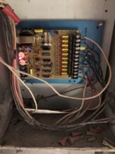
Fig. 2 – Example of aged baghouse control board
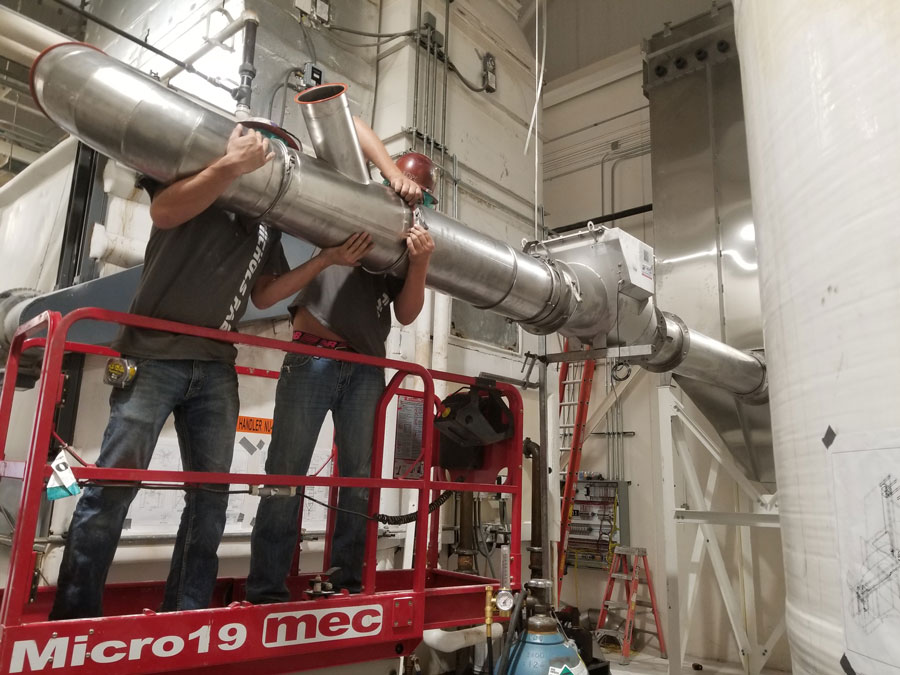
Applied IoT gateway technology solution: All control boards were removed from the baghouse and an IoT controller was implemented (Fig. 3). A differential pressure gauge was installed to read pressure across all three dust collectors as if they were a three-compartment single baghouse. At that point, the customer was able to change the baghouse to clean-on-demand, which helped balance airflow across all three baghouses, helping to optimize flow from the crusher. Customer began to utilize pulse count totals on cleaning system (Fig 4) to predict filter life as mechanical failure from cleaning cycles was traditionally their mode of failure.
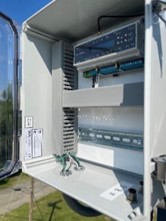
Fig. 3 – Field installation example
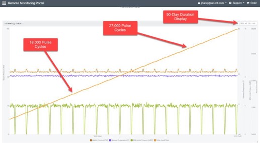
Fig. 4 – Example of tracking pulse valve activation count through filter life cycle
The customer also installed a thermocouple on the fan bearing. This signal was incorporated into the IoT gateway, and low-level and high-level alarms were established. The thermocouple sends a signal to the IoT gateway, and notifications are sent via text and email to the correct team of people within the company. This has allowed them increased control, more uptime, and increased availability of their crusher and virtually eliminated unscheduled downtime to allow the crusher to cool down. Using the Gateway technology, the thermocouples can be loop powered from the gateways to reduce wiring and electrical costs.
B. Example 2: Metal Dust in Process Equipment
Previous State: Customer handles dangerous dust that requires forced air when working around process conditions. Any build- up of material can lead to a thermal upset condition, causing smoldering in the duct and process equipment. Old and outdated controls were not providing accurate measurements of flow, pressure, or rotation (for airlocks). Filters were damaged and changed out frequently, even when there were power outages that would cause air moving devices to shut down. Manual monitoring had even caused a recorded safety event while having to climb ladders to the equipment. Additional concern was noted from high lead exposure in the area.
Applied IoT gateway technology solution: IoT gateway control systems were installed and programmed to include push notifications to maintenance team of power loss. This allowed maintenance team to prevent fires from occurring in process equipment that previously went unknown. Customer integrated airflow monitors into their gateway system and utilized it to confirm hazardous dusts are being pulled from personnel areas.
Customer used their portal gateway to build a customized notification system for maintenance personnel for certain alarms and high-level warnings pushing out to a larger group of personnel, including management. This allows for proper manpower to be applied to critical systems well before the previous catastrophic events could occur, such as header pressure loss (Fig. 5). Having a universal system that worked across sensor brands and unlimited user access was key in the decision making
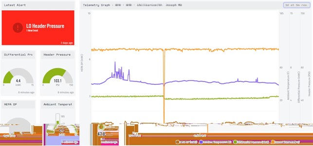
Fig. 5 - Example of Web Portal Display of Header Pressure Loss
C. Example 3: Transfer Silo and Material Storage – Alternative Fuels
Previous State: Customer had multiple filter receiver baghouses collecting wood dust and other natural materials. System was moving air and product, but filters inside baghouse were crushing (Fig. 6) under an unknown amount of pressure. Baghouse cleaning system was fully functional, but customer could not determine any root cause of performance issues in baghouse. Once the filters crushed, there was almost no airflow through the baghouses, and the mechanical failure and replacement of filters was happening far too often, and equipment was offline.
Before IoT implementation, human error was identified, but only after an upset condition when the cleaning system was not taken out of isolation following a filter installation. This condition was reflected again in the solution state.
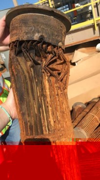
Fig. 6 – Filter crushed from high dP event
Applied IoT gateway technology solution: A full suite of IoT gateway baghouse controls was installed to replace the existing control system. Once installed, a custom cleaning cycle was programmed to clean only when certain dP levels were seen in the filter receivers. Trending of the dP was observed, and high-pressure conditions were programmed into the push notifications, notifying maintenance personnel in real-time, via text message, (Fig. 7) that dP was increasing at a rapid rate (Fig. 8) and compressed airflow had been left off.
Once the customer observed these trends, as well as temperature trends, they were able to identify fuel and raw material changes that were causing significant build-up issues within their process. Maintenance issues persisted as well, but were identified within minutes, not hours or days as the Previous State.
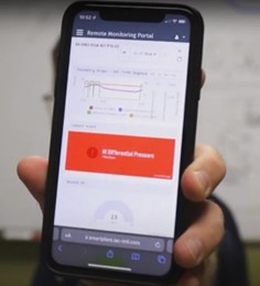
Fig. 7 – Example of onscreen alert mobile display
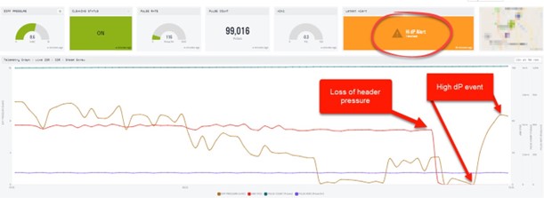
Fig. 8 – Onscreen representation of high dP even seen in connected web portal
VI. CONCLUSION
When considering the use of cloud-connected remote monitoring devices, remember the five goals. Will it connect with ease? Will it collect the data you want? Will it help you predict non-optimal issues you’ve been living with for years? Will it help your plant performance improve? Will it work with all sensor or equipment brands, multiple locations and worldwide? The answer needs to be yes for all of the above questions. Your provider should also have industry knowledge, expertise, availability, and manpower to provide the experienced technical support you need when you receive notifications from your IoT gateway cloud- connected systems. Understanding the process is as important as installing the right system. Things don’t change quickly in most industrial manufacturing processes, but IoT technology has arrived, and with the right approach, it can empower your personnel to work smarter than ever before.