When discussing pneumatic conveying systems, handling the "ends of the line," both the feed end (where material enters the system) and the discharge end (where material exits the system), is essential for efficiency, reliability, and maintaining product quality. Here’s a comprehensive guide on how to approach both ends, focusing on the initial feeding of material into the line and the effective removal of solids from the conveying gas at the discharge end.
|
IAC has been designing, fabricating, and installing pneumatic conveying systems since 1987. Our Bulk Material Handling division is at your service for everything from engineering evaluations and upgrades on existing systems, to integration and installation of new or expansion pneumatic conveying systems. Contact us today for all your pneumatic material handing needs!
|
|
| This article was created for IAC's sponsorship of the Powder and Bulk Solids Magazine 2024 Dry Pro Webinar on Pneumatic Conveying titled, "Feeding and Filtration in Pneumatic Conveying Applications". | This webinar is available for viewing until April 2025. Learn more on PBS's Webinars page. |
Input: Feeding Material into the Pneumatic Conveying Line
At the feed end, the primary goal is to introduce the bulk material into the system’s stream of conveying gas consistently and reliably. This can be challenging due to varying material characteristics, which can affect how a material behaves when being fed into a conveying line. Properly managing this phase ensures smooth operation and prevents blockages or damage to the system.
Material Characteristics and System Integration
For this article we'll skip going into detail on material characteristics, and simply state that understanding the physical and chemical properties of the bulk material to be conveyed, such as particle size, shape, bulk density, and moisture content is important. These characteristics influence the choice of feeder device(s) and conveying method (dilute phase or dense phase).
Additionally, for certain materials, particularly those that are very fine or tend to pack, adding aeration to the feed mechanism helps fluidize the material, facilitating easier entry into the conveying line.
You'll also want to ensure sound system integration by checking that the feeder device is compatible with the conveying system in terms of both performance and control logic. We have experts in PLC programming and Automation Control Systems available who can help in this area - just contact us!
Need help with modifying or designing a pneumatic conveying system? IAC's Application Data Sheet for Pneumatic Conveying Systems will step you through the most common information you'll need to know when you contact us about your pneumatic conveying needs. Don't worry if you don't have all the answers - we're here to help! Contact us today for your free, no obligation project bid.
|
PNEUMATIC CONVEYING FEED-END CASE STUDY: In 2023, IAC’s Bulk Material Handling Group was awarded a dilute phase pneumatic conveying project contract from a specialty metals coating manufacturer for the engineering, supply, installation, and start-up of a feed-end product batching system. The bulk density of the 24 micron sized materials to be conveyed ranged from 51 to 39 lbs/cubic feet, and the convey rate equaled 8,000lb/hr instantaneous. |
 |
 |
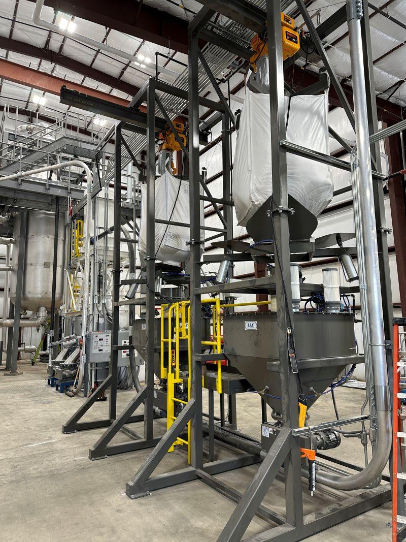
The project’s scope started with designing two (2) FIBC unloading stations to fit the customer’s available vertical space. The stations included safety handling fixtures, paddle style massage plates for the lower end of the bags, and containment hoppers equipped with dual level probes and pneumatic flow aids. An HMI control panel allows the operator to set the product variable points and start the batching operation. The automated controls of the pneumatic conveying system were programmed to alternate the metered flow of product from each containment hopper to a single filter receiver, which held the materials in its hopper until discharged into an available mixer. Once the first mixer started its cycle, the batching system released the next round of materials for the second mixer, and the process repeats with zero mixer downtime. |
|
The mixers were fitted with a discharge chute and a rotary airlock valve with a surge hopper to accept the full volume of the materials quickly. The airlock valve was programmed to meter the discharged materials directly onto a conveyor for delivery to the downstream fluid bed dryer. IAC guaranteed the system to convey at a minimum of 7,920 lb/hr to the fluid bed dryer. Powering the pneumatic conveying system was a heavy duty, tabletop mounted pressure blower package equipped with an efficient 30 hp blower motor mounted on an adjustable base for easy belt tensioning. It was sized for 521 ICFM @ 5.1 PSIG outlet pressure. The pressure blower package was placed inside a sound enclosure built from marine grade 5022-H32 aluminum, designed to allow a maximum outside sound level of 85dBA or below, measured at three (3) feet. The enclosure was built with an insulated pitched roof, and a ventilation fan to provide cooling air draft across its interior chamber. |
 |
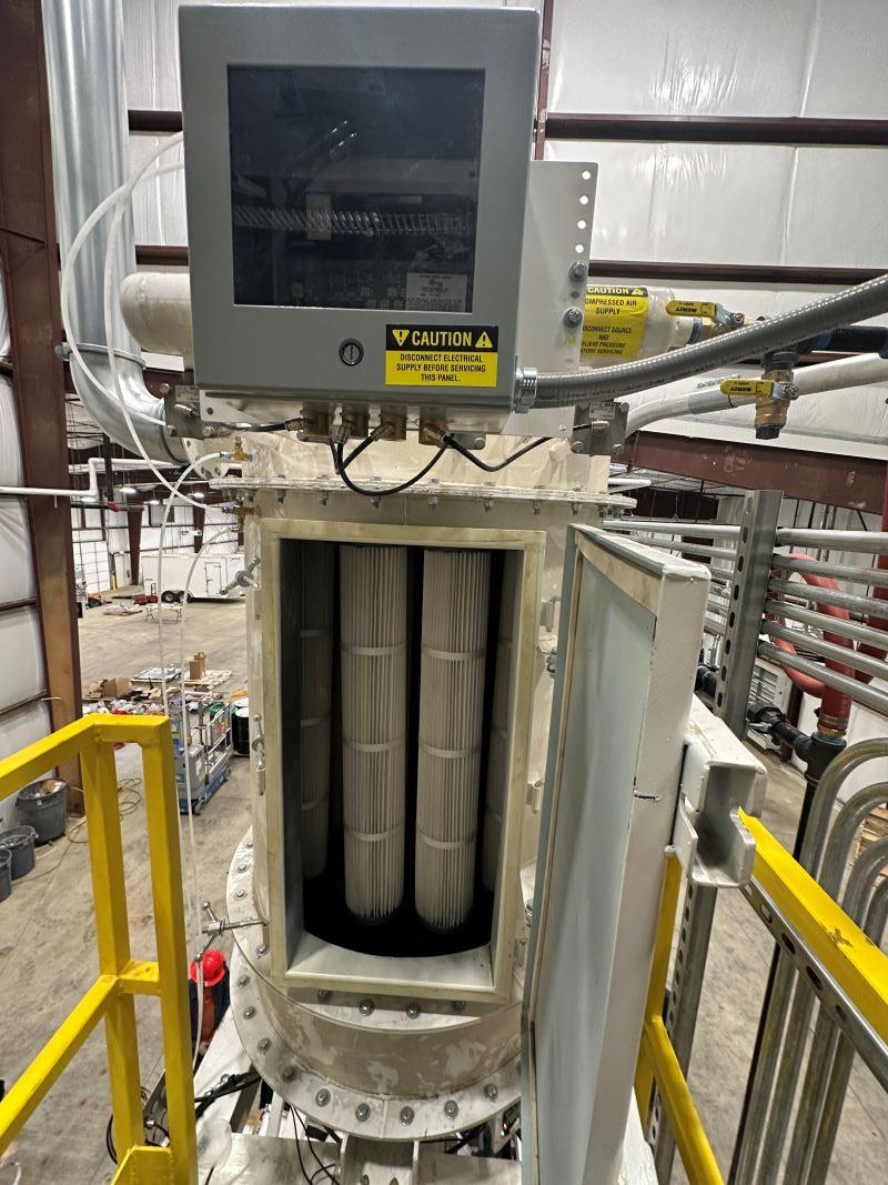 |
All piping, convey lines, airlock and valves, clean air lines, and other materials to build the system were supplied by IAC. The 40” diameter filter receiver was an IAC OEM product built to withstand continuous +/- 16” hg. Features included side access doors for ease of maintenance, quantity fourteen (14) bottom load, 40” long polyester pleated filter elements, cast iron SMART pulse jet diaphragm valves for low compressed air use, conical hopper, and advanced controls such as the timer control panel, level probe, and gauges. To save costs on the project, minor modifications were made to the company’s existing dual mixer arrangement so that it could continue to be used with the new batching system. IAC supplied all the necessary equipment to make the modifications. |
Types of Feeding Devices for Pneumatic Conveying Systems
Choose a feeder that can provide a consistent and controllable feed rate suitable for the material characteristics and specifications of the pneumatic conveying system. Types of feeder devices include:
1. Rotary Airlock Valves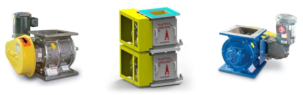
Also known as a rotary airlock, rotary valves are designed to handle a wide range of bulk solid materials, from powders to granules. Their robust design allows them to deal with different material characteristics, such as abrasiveness or cohesiveness, making them a versatile choice for various types of pneumatic conveying systems Rotary valves have two primary functions; provide a seal to maintain a proper airlock condition within the system while allowing material to pass from a hopper into the conveying line.
The design of a rotary airlock typically includes a rotating element with pockets or vanes that pick-up material from an inlet, and release it at its outlet, thus metering the flow of bulk solids. By controlling the speed of rotation, you can adjust the rate at which materials are fed into the conveying line, ensuring a consistent and controlled flow that matches the system's requirements.
Rotary valve feeders also solve one of the key challenges in pneumatic conveying, which is maintaining a pressure differential between different parts of the system, or between the system and the external environment. It's design acts as an airlock, allowing solid material to pass from one pressure zone to another while minimizing air flow. In systems where there's a risk of material backflow or blowback, such as when material feeding and conveying occur simultaneously, a rotary valve also serves as a physical barrier, preventing materials in the conveying line from moving back towards the feed hopper or other upstream equipment.
By ensuring a steady, controlled flow of materials into the conveying system, rotary valve feeders help optimize the conveying efficiency. This reduces energy consumption and wear on the system components, contributing to lower operational cost.
How do you make smart buying decisions when it comes to a pneumatic conveying system? IAC's Bulk Material Handling Operations Manager Nathan Petrie answers this question in the article, "Smart Buying Decisions for Pneumatic Conveying Systems".
2. Screw Feeders
The primary function of a screw feeder is to accurately meter the correct amount of material into the pneumatic conveying system. This is essential for maintaining the desired conveying rate and ensuring that the system operates efficiently. By controlling the flow of material, the screw feeder helps prevent blockages in the system and ensures a steady, controllable flow of material.
Often, bulk materials are stored in a hopper or a similar storage unit before they are fed into the pneumatic conveying system. The screw feeder extracts these materials from the hopper and transports them into the conveying line. Its design ensures that materials are drawn out evenly, preventing surges or gaps in the material flow that could affect the conveying process.
As the screw turns, it can also compact and de-aerate the material, which is particularly useful for fluffy or aerated products. This process makes the material more dense, reducing the volume of air required for conveying and, therefore, the energy consumption of the system.
The design of a screw feeder allows for adjustable feed rates. By varying the speed of the screw, operators can precisely control how much material enters the pneumatic conveying system over time. This flexibility is crucial for processes that require precise ratios of materials or for systems that need to accommodate varying processing capacities.
Screw feeders can also act as a form of isolation between the processing environment and the pneumatic conveying system. This is particularly important in applications where preventing air from entering a hopper or maintaining a controlled environment within the hopper is necessary.
Screw feeders are versatile and can handle a wide range of material types, from powders and granules to small solids. Their design can be customized with different screw profiles and pitches to accommodate the specific characteristics of the material, such as its bulk density, particle size, and flowability.
3. Pressure Tanks
A pressure tank feeder, also known as a pressure vessel or blow tank feeder, temporarily stores a certain quantity of the material to be conveyed. They are primarily used in dense phase pneumatic conveying systems, but can also be used in certain dilute phase conveying applications depending on the specific requirements of the material to be conveyed.
As the name suggests, the tank is capable of being pressurized. It is equipped with valves and air inlets to facilitate this pressurization. Once the tank is pressurized, and the exit valve to the conveying line is opened, the material is forced out of the tank and into the conveying line by the pressure differential.
Pressure tank feeders are particularly well suited for conveying materials that are difficult to handle, such as abrasive, fragile, or very fine materials. The ability to control the feed rate and pressure allows for the gentle handling of materials, minimizing degradation or damage. Furthermore, for very fine or powdery materials, the controlled environment of a pressure tank feeder helps in managing issues related to fluidization or aeration of the material.
The closed system of a pressure tank feeder provides an additional safety benefit for materials that are potentially hazardous or sensitive to environmental conditions. Since the material is contained within the tank and conveying line, risk of exposure to the surrounding environment or personnel is minimized. The sealed nature of the system also protects against moisture or air ingress, which can be critical for hygroscopic or moisture-sensitive materials.
Compared to other mechanical conveying systems, pressure tank feeders, especially when used in dense phase pneumatic conveying systems, can be more energy efficient for certain materials and distances. Dense phase conveying, facilitated by pressure tank feeders, requires lower velocities and, consequently, can result in lower air consumption and reduced wear on the conveying line and material. This efficiency translates to reduced operational costs and longer system lifespan.
4. Vibratory Feeders
A vibratory feeder is designed to handle a wide range of materials, from fine powders to large, coarse particles. It has a feeding tray or tube that vibrates at a controlled frequency and amplitude, provided by electromagnets or pneumatic (air-cushioned) pistons. The vibration induces a flow of materials out of the feeder and onto a subsequent process or conveying line.
The vibration intensity and frequency can be finely tuned, allowing for precise control over the volume of material being delivered into the pneumatic system. They also help in promoting the flow of materials that are prone to bridging or arching in storage bins or hoppers. The vibration helps to break apart material clumps and encourage flow, preventing blockages in the hopper and ensuring a steady supply of material into the pneumatic conveying system.
Vibratory feeders are adaptable to different segments of the pneumatic conveying process. Whether the system is designed for dilute phase conveying, where materials are suspended in the air stream, or dense phase conveying, where materials are pushed or pulled along the convey line, vibratory feeders can be configured to meet the specific needs of each application.
5. Venturi Feeders
A Venturi feeder, also known as a Venturi eductor or injector, operates based on the Venturi effect—a principle of fluid dynamics where fluid pressure decreases as it flows through a constricted section of pipe. They can handle a wide range of materials, including abrasive, fragile, or mixed substances, by adjusting the conveying conditions.
The primary function of the Venturi feeder is to introduce (or inject) the bulk material into the conveying line.
As compressed air (or any conveying gas) is forced through the narrow throat of the Venturi feeder, its velocity increases, creating a reduction in pressure according to Bernoulli's principle. This pressure drop generates a vacuum at the point where the material is fed into the system. The vacuum sucks the material into the conveying line, mixing it with the high-speed air.
The geometry of the Venturi feeder (e.g., the diameter of the throat) accelerates the air-material mixture. After material is introduced at the feeder's throat, it gets accelerated as the air (or conveying gas) speed increases. This acceleration is crucial for ensuring the material is carried along with the airflow throughout the system.
A Venturi feeder efficiently utilizes the energy from the compressed air to both convey the material and control its feed rate without the need for mechanical moving parts. This can significantly reduce the maintenance required and the potential for breakdowns, making the system more reliable and cost-effective in the long run.
Venturi feeders have a straightforward design that can be easily integrated into existing systems. Their compact size makes them particularly advantageous in settings where space is limited.
Output: Separation Technologies for Discharging Bulk Materials from a Pneumatic Conveying System
The output devices in pneumatic conveying systems are critical for ensuring the smooth discharge of materials from the system to the desired location or processing equipment. Here is a look at some of the primary types of output devices used in these systems:
1. Rotary Valves
Rotary valves, described above, are used as both input and output devices.
2. Cyclone Separator
The primary job of a cyclone is to separate particulate matter from the air stream. As the mixture of air and particles enters the cyclone, the design of the cyclone creates a centrifugal force that causes the particles to move outward towards the wall of the cyclone due to their inertia.
Once particles are pushed against the wall, they lose momentum and, due to gravity, fall down into a collection hopper located at the bottom of the cyclone. This process effectively removes particles from the airflow, allowing for the clean air to be vented out or recirculated back into the system, minimizing material loss and reducing the load on any downstream filtration equipment.
The cyclone also helps in managing the airflow within the pneumatic conveying system. By removing particulate matter, it ensures that the air can be reused in the system, helping to maintain efficient operation and reducing the need for additional air treatment or filtration.
By removing abrasive or potentially damaging particles from the air stream, cyclones protect downstream equipment, such as fans, blowers, and other machinery, from wear and tear. This prolongation of equipment life is crucial for maintaining operational efficiencies and reducing maintenance costs.
Cyclones help in achieving environmental compliance by controlling dust and particulate emissions. This is particularly important in industries where dust can pose health risks or environmental hazards. In summary, the job of a cyclone in a pneumatic conveying system is to efficiently separate and remove particulate matter from the air stream, thereby protecting equipment, managing airflow, ensuring the quality of conveyed materials, and helping to meet environmental regulations. Cyclones are valued for their simplicity, durability, and efficiency in a wide range of industrial applications.
3. Filter Receiver
|
The primary function of the filter receiver is to efficiently separate the conveyed material from the airflow, ensuring that the bulk material is collected and not lost to the exhaust. This is crucial for minimizing product waste and maximizing efficiency in material handling operations. After separating the bulk material, the air or gas used for conveying needs to be cleaned of any remaining dust or fine particles before it is vented to the atmosphere or recirculated back into the system.The filter receiver contains filtration media (e.g., filter bags or cartridges) that trap these particles, allowing only clean air/gas to pass through. This is important for environmental compliance and for maintaining air quality standards. |
|
By capturing fine particles and preventing them from being released into the environment or back into the system, the filter receiver protects downstream equipment and operators from potential harm or damage that could be caused by dust and other particulates.
In some systems, the filter receiver also helps to maintain the pressure balance within the pneumatic conveying system. By controlling the air flow through the system, it can help ensure that materials are conveyed at the correct velocity and with minimal degradation.
READ MORE: CASE STUDY OF CYCLONE TO FILTER RECEIVER CONVERSION
4. Dry Scrubber
In a pneumatic conveying system, a dry scrubber plays a vital role in air pollution control by removing or neutralizing hazardous components from exhaust gases before they are released into the atmosphere.
The process involves the interaction of the polluted gas stream with a dry reagent or sorbent, such as lime or activated carbon, which absorbs or chemically reacts with the pollutants, effectively scrubbing them from the gas.
Pneumatic conveying systems, depending on the materials being conveyed, can generate dust and other particulates. A dry scrubber can capture these particulates, preventing them from being emitted into the air.
Certain materials conveyed in these systems can release harmful gases or vapors. Dry scrubbers neutralize acids, such as hydrochloric acid (HCl) and sulfur dioxide (SO2), and control the release of volatile organic compounds (VOCs) and hazardous air pollutants (HAPs).
By removing abrasive and corrosive gases and particulates, dry scrubbers also contribute to the protection of the pneumatic conveying system itself and other associated equipment. This can reduce maintenance costs and extend the life of the system.
5. Wet Scrubber
Like a dry scrubber, a wet scrubber removes particulate matter and/or gaseous pollutants from the exhaust stream before it is released into the atmosphere.
The wet scrubber uses water or another liquid to capture and remove particulate matter from the exhaust gas. As the dirty gas stream passes through the wet scrubber, it comes into contact with the scrubbing liquid. Particles are captured in the liquid, primarily through mechanisms such as inertial impaction, diffusion, and/or interception.
Besides removing particulates, wet scrubbers can also absorb and neutralize gaseous pollutants. This is achieved by dissolving or chemically reacting to the gas with the scrubbing liquid.
Wet scrubbers can also cool down hot exhaust gases as they pass through the scrubber, which can be an additional benefit in certain applications. The evaporation of the scrubbing liquid reduces the temperature of the gas stream.
Wet scrubbers are chosen based on specific application needs, including the type and size of particulates, the presence and type of gaseous pollutants, and the required efficiency of removal. They are available in several designs, including venturi scrubbers, packed towers, and spray towers, each offering different efficiencies, pressure drops, and operational characteristics suitable for various applications.
Thank you for your interest in IAC's pneumatic conveying products and services. If you have any questions on systems for the feed or discharge ends of pneumatic conveying systems, please contact us!